| XLE SERIES | PRECISION ELECTRIC |
 |
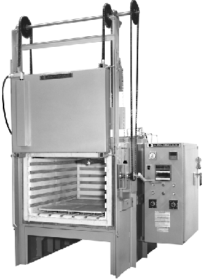
APPLICATIONSThe XLE Series are highly uniform and controllable electric box furnaces widely adaptable to many applications. In the heat treating field these include hardening, neutral hardening, solution heat treating, stress relieving, annealing, aging, precipitation hardening, and tempering. In the ceramic field applications include ceramic bisque firing, thin film processing, glazing, and decorating. Brazing, calcining, drying, melting of glass and metals, glass annealing and bending, enameling, and sintering are just some of the other applications XLE furnaces are used for. Although "standard" configurations are made, each furnace is normally fitted with standard and special options to suit specific needs. These include vertical doors, fans, cooling venturis, vents, special hearths, racks, baskets and loading devices, quenching systems, various controlled atmospheres, retorts, viewing ports, special element alloys, special thermocouples, various kinds of alarms, program controls, and recorders. |

A PHOTO SHEET SHOWING
VARIOUS XLE FURNACES
AND OPTIONS
This is a PDF File which will Open up automatically in Netscape 4.X or Explorer 4.X and above

A SPECIAL XLE FURNACE
WITH EXTERNAL AIR QUENCH
AND PROTECTIVE ATMOSPHERE
FOR NEUTRAL HARDENING
OF AIR HARDENING TOOL STEEL
This is a PDF File which will Open up automatically in Netscape 4.X or Explorer 4.X and above
FEATURES
FAST HEAT UP & COOL DOWN
An empty furnace will heat up to 2000F (1093C) in approximately 1-1/2 hours.
The high K.W. (superpower) option will trim this to 1 hour. Cool down to 500F (260C) is
approximately 5 hours. Optional 300 or 600 CFM venturi will speed cooling.
EXCELLENT UNIFORMITY
The furnace is uniform to within +/-20F (+/-10C) above 1400F (760C) within
the Uniform Working Dimension (see specification chart). Optional fan systems are
available for tighter uniformity of up to +/-5F.Tighter uniformity is also achieved by
reducing the working dimensions and with multi-zoning.
TEMPERATURES TO 2350F
With optional nickel-chrome elements the maximum temperature is 2100F(1134C.)
Some options such as fans and other alloy components may also limit the temperature.
 |
PRESHAPED BRICK SECTIONS SAVE ON HEAT LOSS AND MAINTENANCE COSTS The refractory is cemented in sections on a very flat table. These sections are then precision cut and routed. All sections fit together with engineered heat locks which improve the insulating integrity of the furnace even after many years of service. Brick sections can easily be installed by in-house maintenance personnel saving on expensive specialized bricklayer labor. EFFICIENT MULTILAYERED INSULATION |
LOW WATT DENSITY ELEMENTS FOR LONG LIFE
The standard elements are coiled from high grade iron-aluminum-chrome alloy
(Kanthal A-1 or the equivalent). Nickel-chrome (80-20), Chromel AA, and other alloys are
available for special atmospheres and applications. A watt density normally below 10 watts
per square inch maximizes element life. (Watt density is the ratio of watts to square
inches of radiating surface area.)
EVEN ELEMENT PLACEMENT
Each element is separately and evenly spaced on the bottom, sides, door and
back. This is the finest method of distributing radiant heat energy at high temperatures.
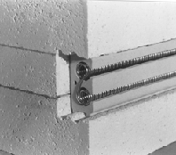
| CERAMIC ELEMENT HOLDERS The elements are supported in proprietary high temperature ceramic element holders. These provide perfect support for the coiled element and excellent radiating characteristics. The smooth surface of the holder prevents premature failure of the element as it expands and contracts. These holders, coupled with a unique all ceramic element terminal, make element replacement easy. Being recessed into the wall of the furnace these elements are not as susceptible to mechanical damage as some other types of element support systems. |
 |
HEAVY DUTY CASE WITH INTEGRATED STAND
The furnace case is constructed of 10 gauge steel with external bracing
angles welded to the entire case and base assembly. Leveling bolts, anchoring holes and
lifting rings are included. The main seams are continuously welded for an attractive
appearance. The entire case is primed inside and out with a high temperature (800F)
silicone based paint. The final coat is a heat resistant light gray-green enamel. Custom
colors are available. Sealed cases for controlled atmosphere use are optional.
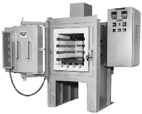
| DOUBLE PIVOTED PLUG DOOR The standard door is a double pivoted horizontal plug door. The double pivoting allows the door to open like a parallelogram which keeps the hot face from the operator. There are two heavy duty clamps for tight sealing. Because of the completely horizontal motion of the door as it is sealing there is no wear on the seal face. The door has a 3/4” refractory plug which protrudes into the furnace chamber and provides a highly effective heat lock. There is a 3-1/2” refractory to refractory seal around the perimeter of the door. Counterbalanced vertical doors with hand crank, pneumatic or electric actuator are options. Vertical doors lift away from the furnace seal before lifting up. They also include a heat locking plug. |
 |
 |
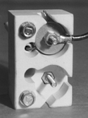
CERAMIC ELEMENT TERMINALS Unique L&L designed all ceramic element terminal blocks allow the element ends to be clamped without twisting the whole end around a terminal bolt, making it easy to remove an element. The connection wires can be easily removed without disturbing the element termination (which allows you to easily isolate an element for a resistance check.) The terminal block features superb electrical isolation characteristics. |
A WIDE VARIETY OF HEARTHS
The standard hearth is one or more 3/4” thick ceramic plates elevated on
ceramic blocks 1-1/2” above the bottom elements. This air space improves uniformity.
Silicon carbide plates, alloy plates, roller hearths, baskets, racks, loaders, castable
piers, air cooling tables and many other loading options are available.
SIDE MOUNTED CONTROL PANEL WITH HINGED DOOR HOLDS ALL COMPONENTS
All temperature controls, relays, contactors, power controls, switches,
transformers and fuses are located in a side mounted NEMA 1 control panel with a gasketed
hinged door. J.I.C. wire coding is used throughout. An oil tight NEMA 13 lighted on/off
push -button switch turns the furnace on. Controls are mounted at eye level for easy
visibility. A NEMA 12 panel with fused disconnect switch is optional. A cooling fan is
included with SCR power controls.
DIGITAL HONEYWELL UDC 2000 PID TEMPERATURE CONTROL
A Honeywell UDC 2000 microprocessor based digital single set point control is
standard. Two full vacuum fluorescent displays include English language programming
information for easy set up. This is one of the easiest digital controls to operate.
Accuracy is .25% of scale. All PID tuning constants (proportioning band, reset, rate) plus
maximum temperature, scale range, thermocouple type and many other parameters are
programmable. Ramp/Soak programming is optional. Many other controls are optionally
available.
DIGITAL HIGH LIMIT CONTROL
A Honeywell UDC 2000 digital high limit control, complete with back up
contactors and separate thermocouple, shuts off furnace if temperature or power control
fail. The digital control allows a maximum temperature to be programmed into the control.
MERCURY CONTACTORS FEATURE FAST CYCLE TIME FOR ACCURATE CONTROL
Other benefits are long contactor life and quiet operation. SCR power
controls are optional.
TWO ZONE CONTROL FOR CLOSE GRADIENTS
The elements are divided into top and bottom zones. The control output is
routed through two input switches to allow adjustment of the total time on to each zone.
There are thermocouples mounted top and bottom with a selector switch to read the
differential. Special designs with up to six zones or more can be used to promote even
greater temperature uniformity.
TYPE K THERMOCOUPLES WITH SHIELDED EXTENSION WIRE
Type K open thermocouples are standard. All thermocouple lead wire is
shielded from electrical noise and grounded to a common ground. Lead wires are carefully
run to avoid interference from power wiring. Inconel sheathed Type K are a commonly
supplied option. Type R and Type S platinum thermocouples are also optional.
MANY SAFETY FEATURES
Thermocouple break protection is included. Limit switches shut off power to
furnace if the door is opened or the power panel back is removed. Control voltage is
transformed to 120 volts. The control and branch power circuits are fully fused.
BUILT IN RELIABILITY
The furnace is warranted for one year except for the elements and
thermocouples (six months.) The control system is burnt in and calibrated at actual
operating temperatures in a test furnace and a recording of this test is provided. As a
result of having made a large number of these furnaces, the engineering thought and detail
devoted to this series is extensive. L&L has paid great attention to small details,
interchangeable parts, serviceability, reliability, adjustments, documentation and
instructions . The design has continuously evolved over 40 years.
EXTENSIVE INSTRUCTIONS AND DOCUMENTATION
Along with the informative J.I.C. wiring diagram, which includes a sequence
of operations and a ladder diagram (for easy troubleshooting), there is an extensively
detailed instruction book with a general dimension and assembly drawing, start up,
installation, operation, maintenance and troubleshooting information.
WORLDWIDE SERVICE
Although these furnaces are designed for easy in-house start up and
maintenance, worldwide factory service and start up assistance is available.
OPTIONS
- CONTROL, RECORDER AND ELECTRICAL OPTIONS
- VERTICAL DOORS: Counterbalanced with hand crank, electric gear drive or pneumatic operator.
- SCR POWER CONTROLS: Single and multi-zone with biasing.
- NEMA 12 CONTROL PANEL: With fused disconnect switch.
- SPECIAL HEARTHS: Silicon Carbide and alloy, baskets, racks, roller hearths, special loading devices.
- VIEWING PORTS
- VENTS AND VENTURIS: Manual or pneumatic dampers, 300 and 600 CFM venturis for fast cooling.
- FANS: Various fans for temperatures up to 2200oF for high uniformity and atmosphere distribution.
- ATMOSPHERE CONTROL: Case is sealed for inert or combustible atmospheres. One option is nitrogen spiked with propane for high decarburization resistance. Alloy retorts for low dew point operation. Atmosphere control systems with safety systems to meet NFPA 86C.
SPECIFICATIONS
| MODEL NUMBER | ACTUAL INSIDE DIMEN | UNIFORM WORK DIMEN | HEARTH DIMEN | EXTERNAL DIMEN | OPT VERT DOOR | STAND | HIGH | STAND LOAD WGHT | APPRX SHIP WGHT | |||||||
| W | H | D | W | H | D | W | D | W | H | D | HGHT | K.W. | K.W. | (LBS) | (LBS) | |
| XLE 524 | 16 | 18 | 25 | 13 | 13 | 20 | 13 | 22 | 54 | 59 | 48 | 99 | 13.5 | 18.0 | 175 | 1600 |
| XLE 814 | 19 | 15 | 25 | 16 | 10 | 20 | 16 | 22 | 57 | 56 | 48 | 93 | 14.0 | 18.0 | 200 | 1700 |
| XLE 816 | 19 | 15 | 37 | 16 | 10 | 32 | 16 | 32 | 57 | 56 | 60 | 93 | 19.0 | 25.0 | 300 | 1900 |
| XLE 824 | 19 | 21 | 25 | 16 | 16 | 20 | 16 | 22 | 57 | 62 | 48 | 105 | 17.0 | 22.0 | 200 | 1800 |
| XLE 836 | 19 | 21 | 37 | 16 | 16 | 32 | 16 | 32 | 57 | 62 | 60 | 105 | 22.5 | 29.0 | 300 | 2100 |
| XLE 848 | 19 | 21 | 49 | 16 | 16 | 44 | 16 | 33 | 63 | 62 | 60 | 105 | 27.0 | 35.0 | 450 | 2200 |
| XLE 244 | 25 | 27 | 25 | 22 | 22 | 20 | 22 | 22 | 63 | 68 | 48 | 117 | 27.0 | 35.0 | 300 | 2100 |
| XLE 246 | 25 | 27 | 37 | 22 | 22 | 32 | 22 | 33 | 63 | 68 | 60 | 117 | 31.5 | 42.0 | 450 | 2400 |
| XLE 248 | 25 | 27 | 49 | 22 | 22 | 44 | 22 | 44 | 63 | 68 | 72 | 117 | 38.0 | 49.5 | 600 | 2800 |
| XLE 272 | 25 | 27 | 73 | 22 | 22 | 68 | 22 | 66 | 63 | 68 | 96 | 117 | 51.0 | 68.0 | 900 | 3500 |
| XLE 448 | 25 | 51 | 25 | 22 | 46 | 20 | 22 | 22 | 63 | 93 | 48 | N/A | 38.0 | 49.4 | 300 | 2900 |
| XLE 3248 | 31 | 27 | 49 | 28 | 22 | 44 | 28 | 44 | 69 | 68 | 72 | 117 | 48.0 | 64.0 | 700 | 3100 |
| XLE 3260 | 31 | 27 | 61 | 28 | 22 | 56 | 28 | 56 | 69 | 68 | 84 | 117 | 55.0 | 71.5 | 850 | 3500 |
| XLE 3272 | 31 | 27 | 73 | 28 | 22 | 68 | 28 | 66 | 69 | 68 | 96 | 117 | 59.0 | 78.5 | 1000 | 3900 |
| XLE 3348 | 31 | 33 | 49 | 28 | 28 | 44 | 28 | 44 | 69 | 74 | 72 | 129 | 48.5 | 65.0 | 700 | 3400 |
| XLE 3360 | 31 | 33 | 61 | 28 | 28 | 56 | 28 | 56 | 69 | 74 | 84 | 129 | 60.0 | 78.0 | 850 | 3800 |
| XLE 3372 | 31 | 33 | 73 | 28 | 28 | 68 | 28 | 66 | 69 | 74 | 96 | 129 | 66.5 | 88.5 | 1000 | 4200 |
| XLE 3436 | 37 | 27 | 37 | 34 | 22 | 32 | 32 | 32 | 75 | 68 | 60 | 117 | 40.0 | 52.0 | 600 | 2900 |
| XLE 3448 | 37 | 27 | 49 | 34 | 22 | 44 | 32 | 44 | 75 | 68 | 72 | 117 | 48.0 | 64.0 | 900 | 3400 |
| XLE 3472 | 37 | 27 | 73 | 34 | 22 | 68 | 32 | 66 | 75 | 68 | 96 | 117 | 66.0 | 88.0 | 1200 | 4200 |
| XLE 3636 | 37 | 39 | 37 | 34 | 34 | 32 | 32 | 32 | 75 | 80 | 60 | 141 | 51.0 | 61.3 | 600 | 3300 |
| XLE 3648 | 37 | 39 | 49 | 34 | 34 | 44 | 32 | 44 | 75 | 80 | 72 | 141 | 56.0 | 66.5 | 900 | 3900 |
| XLE 3672 | 37 | 39 | 73 | 34 | 34 | 68 | 32 | 66 | 75 | 80 | 96 | 141 | 82.0 | 109.0 | 1200 | 4800 |
| XLE 4060 | 42 | 39 | 61 | 39 | 34 | 56 | 36 | 56 | 79 | 80 | 84 | 141 | 70.0 | 91.0 | 1000 | 4600 |
| XLE 4080 | 42 | 39 | 81 | 39 | 34 | 76 | 36 | 76 | 79 | 80 | 104 | 141 | 96.0 | 125.0 | 1500 | 5400 |
| Dimensions are in inches. External dimensions include typical control panel mounted on right side. Specify voltage. 480 volts is standard; 208, 240, 380 and 575 volts are optional. 3 phase is standard; single phase is available. 60 or 50 Hertz. Heat Loss is total K.W. lost per hour at 1800F/968C. Heat Storage is the total K.W. it takes to heat furnace up to 1800F/968C. Multiply K.W. by 3412 to get BTUs. Heavier loading weights are optional. Tighter uniformity can be achieved by using a smaller portion of the work space. Specifications are subject to change without notice. | ||||||||||||||||