|
Thermal Dilatometric
Analysis (TDA), often called "dilatometry", measures
the dimensional change of a material (ceramics, glasses, metals,
composites, carbon/graphite, minerals, polymers, and others) as a
function of temperature. This test determines both reversible and
irreversible changes in length (expansion and shrinkage) during
heating and cooling, and pinpoints where reactions occur that cause
expansion or contraction. Samples are quickly and easily measured for
determining firing ranges and firing schedules, measuring thermal
expansion ranges for glaze fits, and measuring thermal expansion
ranges for R&D, QC or product certification. Orton dilatometers
are used for ASTM E-228 testing.
A. Characteristics or
Properties Measured
Coefficient of Thermal Expansion (CTE),
softening point, glass transition temperature, curie point,
crystalline transformation, phase transition, shrinkage, warping,
bloating, sintering rate, isothermal creep, stress relaxation.
The test results are a graph of the TDA signal (converted to percent
length change) on the Y-axis plotted versus the sample temperature in
°C on the X-axis. Sample graphs of enhanced output are shown below.
| Examples of
Applications |
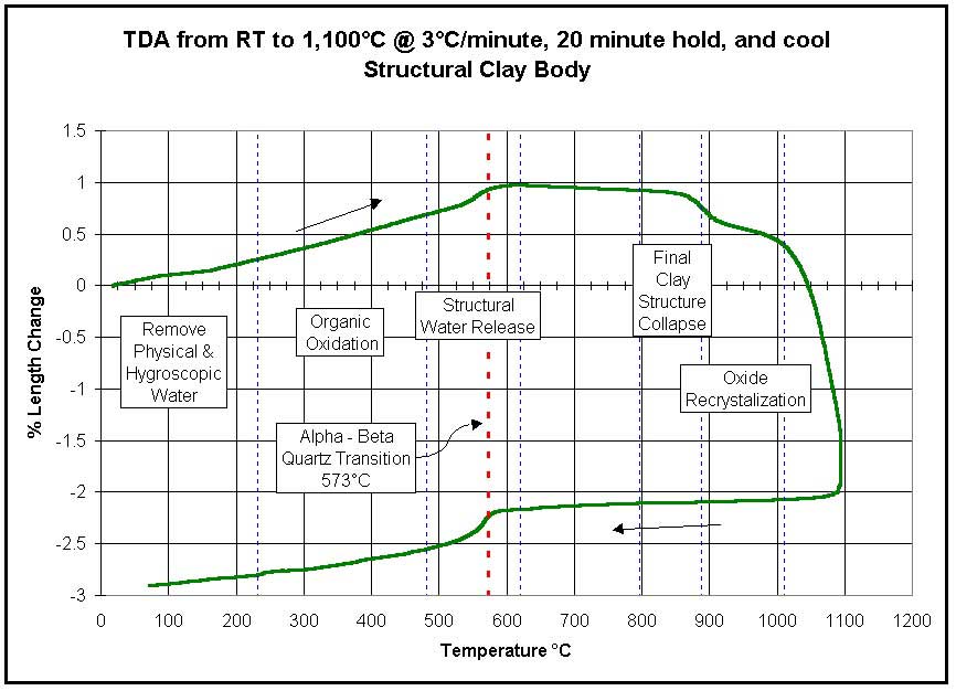
Ceramics - ASTM E-228 |
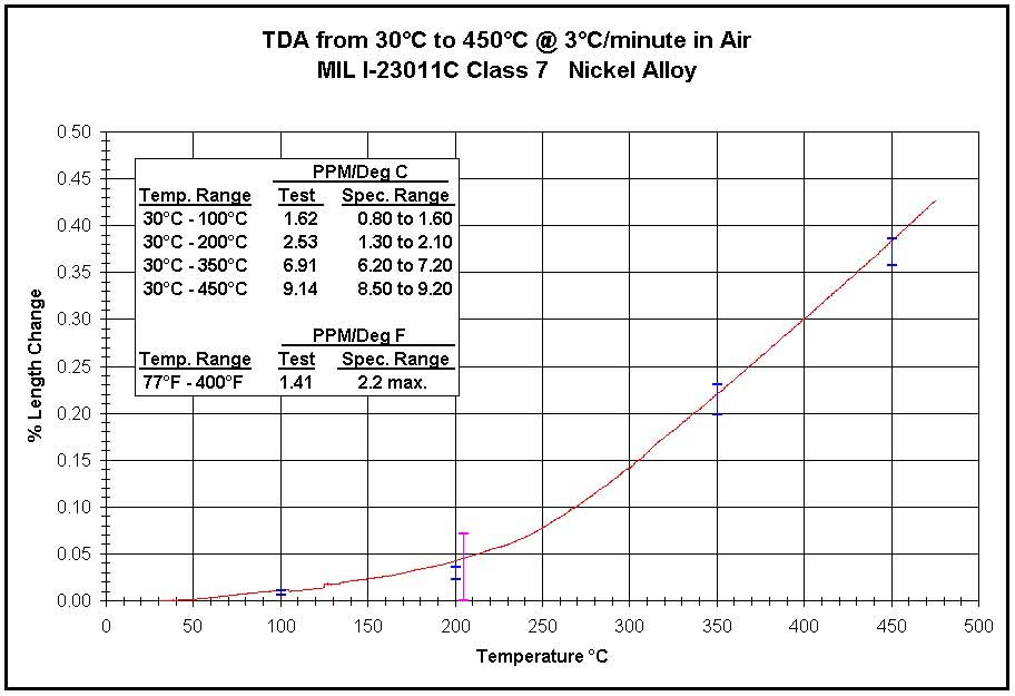
Metals MIL I-23011C Class 7 |
| Range of TDA Test Conditions: |
- -150°C to +1,600°C
- Ambient, Inert, Reducing Atmospheres
- Simple Heat-up and Cool-down, Iso-thermal Holds,
Programmed Thermal Cycles
|
B. Standard Dilatometers
| Standard,
Single Sample, Horizontal Dilatometers |
 |
DIL
2010 B |
DIL
2010 C |
DIL
2010 STD |
DIL
2012 STD |
DIL
2016 STD |
| Temperature Range |
RT to 1,000°C |
RT to 1,000°C or
-170°C to +300°C |
RT to 1,000°C |
RT to 1,200°C |
RT to 1,600°C |
| Furnace |
Kanthal - Tube |
Nichrome - Split Shell
Cryogenic Chamber |
Kanthal - Tube |
Kanthal - Tube |
Silicon Carbide - Tube |
| Thermocouple |
Type "N" |
Type "N" |
Type "S" |
Type "S" |
Type "S" |
| Sample Holder and Probe Rod |
Fused Quartz |
Fused Quartz |
Fused Quartz |
High Alumina |
High Alumina |
| Sample Size (max) |
50 mm long by
20 mm diameter |
100 mm long by
10 mm diameter |
100 mm long by
20 mm diameter |
50 mm long by
20 mm diameter |
50 mm long by
20 mm diameter |
| Contact Load |
113 grams |
Adjustable
4 grams min. |
Adjustable
4 grams min. |
Adjustable
4 grams min. |
Adjustable
4 grams min. |
| Temperature
Control |
Orton
Multi-segment Controller |
| Data Acquisition |
Orton
On-board Computer |
| Data Analysis |
Orton
Analysis Software (Windows 95/98/2000 Based) |
| Computer
Interface |
RS232
Cable |
| Controlled
Atmosphere Option |
Not
Available |
Yes |
Yes |
Yes |
Yes |
| Power
Requirements |
120
VAC, 15 amp, 50/60 Hz |
120
VAC, 15 amp, 50/60 Hz |
120
VAC, 15 amp, 50/60 Hz |
120
VAC, 15 amp, 50/60 Hz |
240
VAC, 205 amp, 50/60 Hz |
*Descriptions and specifications are subject to
change without notice.
 |
Other Orton Dilatometers
• Vertical
• 2 Sample
• Multiple Sample
• Non-contact Laser
• Rapid turnaround
• Quench (metallurgical)
|
 |
Contact Orton for more
details.
C. Computer Analysis
Every Orton dilatometer is supplied
with the software to add to the user's PC in order to acquire, save
and analyze the data generated by the dilatometer. The Orton
Dilatometer Software is a Visual Basic executable routine written for
Windows 95/98/2000 based personal computers. It can be used to monitor
the dilatometer test in real time, or can be used to examine the test
data after the run. The software imports the data through the RS232
interface, and stores it on the hard drive for immediate or
post-testing analysis. The software enables the user to:
View the dilatometer data in a variety of
presentations
- percent linear change (PLC) vs.
temperature
- percent linear change (PLC) vs. time
- first derivative of the percent linear
change (DCE) vs. temperature
- first derivative of the percent linear
change (DCE) vs. time
- percent linear change (PLC) and first
derivative of the percent linear change (DCE) vs. temperature
- percent linear change (PLC) and first
derivative of the percent linear change (DCE) vs. time
Perform a variety of analyses
- calculate the coefficient of thermal
expansion (CTE) between specified temperatures, or a series of
specified temperatures
- calculate the average coefficient of
thermal expansion from room temperature to a specified temperature
at a specified temperature increment
- determine transition temperature
- determine softening temperature
- locate alpha-beta quartz transition
Export the data in a text file format for independent analysis or
archiving purposes
D. Additional
Information on TDA
All materials expand and contract as a function
of temperature. For two materials to adhere to each other, such as
glass to metal seals, metalizations to substrates, and glazes to
bodies, their respective thermal expansion characteristics must be
known, matched, and controlled. Thermal Dilatometric Analysis (TDA),
often called Dilatometry, measures the amount of dimensional change of
a material (ceramics, glasses, metals, composites, carbon/graphite,
minerals, plastics, and others) during a controlled thermal cycle.
Dilatometry measures the normal expansion and contraction of a
material, including its reversible phase changes. This procedure also
measures the irreversible changes in length that are the result of
decompositions, phase transformations, and other chemical reactions,
and helps identify the temperature ranges of those events and
reactions. Such testing is helpful when trying to control the thermal
expansion characteristics of various lots of materials, and in
determining drying and firing schedules.
| Principle of Operation |
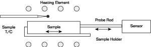 |
The sketch above shows the concepts of a
dilatometer. A sample specimen is placed between the end of the sample
holder and the end of the movable probe rod, and the furnace is heated
according to a pre-programmed thermal cycle. As the sample temperature
changes (as recorded by the sample thermocouple), the sample expands
(pushing against the probe rod) or shrinks (pulling away from the
probe rod). The probe rod transmits the amount of sample movement to
an electronic displacement sensor located outside of the heated
chamber. The displacement sensor generates an electronic signal
corresponding to the positive or negative change in sample length and
continuously sends the signal to the computer. The computer converts
the signal to the percent of length change (%DL) and saves it along
with the elapsed time and the sample temperature. The basic TDA curve
is generated by plotting the percent of length change (%DL) on the
Y-axis against the sample temperature.
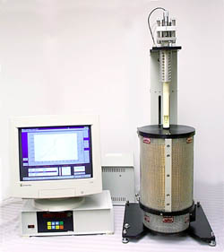
| Horizontal
Dilatometer |
 |
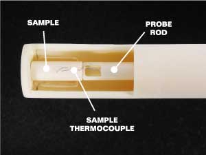 |
The photos above are a horizontal
dilatometer with the furnace moved away to expose the sample holder,
and a close-up view of the sample holder. The photo on the right shows
how the sample is positioned between the end of the sample holder and
the probe rod. After positioning the sample in the sample holder, the
furnace is moved horizontally to surround the sample and sample
holder.
The probe rod extends from the end of the
sample, throught the sample holder tube, and connects to the
displacement sensor assembly outside the furnace. The probe rod is
spring loaded outside the furnace to keep it in constant contact with
the sample, even when shrinking.
The main advantage of the horizontal system
is the uniform temperature zone for the sample. Most dilatometer tests
are performed with a horizontal unit.
Vertical Dilatometer
For larger samples, such as structural clay
bodies, a vertical 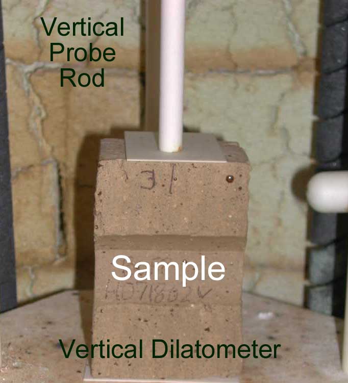 dilatometer
is used. The sample is placed into the furnace and the vertical probe
rod is lowered to contact the sample (as shown in the photo at the
right). The furnace is heated according to the pre-programmed thermal
cycle. As the sample temperature changes, the sample expands, pushing
up on the probe rod, or shrinks, pulling away from the probe rod. The
probe rod is vertically suspended and counterweighted so that gravity
keeps it in constant contact with the sample. The probe rod transmits
the amount of sample movement to the electronic displacement sensor
located overhead and outside the furnace. dilatometer
is used. The sample is placed into the furnace and the vertical probe
rod is lowered to contact the sample (as shown in the photo at the
right). The furnace is heated according to the pre-programmed thermal
cycle. As the sample temperature changes, the sample expands, pushing
up on the probe rod, or shrinks, pulling away from the probe rod. The
probe rod is vertically suspended and counterweighted so that gravity
keeps it in constant contact with the sample. The probe rod transmits
the amount of sample movement to the electronic displacement sensor
located overhead and outside the furnace.
E. Frequently Asked Questions:
Percent Length Change (PLC)
and Coefficient of Thermal Expansion (CTE): Percent Linear
Change (PLC) is the amount of expansion or shrinkage expresses in
percentage of an initial length. A standard TDA curve is usually the
PLC on the Y-axis and the temperature on the X-axis. The thick, black
line in the graph below is a typical TDA curve of glass.
Temperature: The temperature range for a
dilatometer is determined by the type of heating element or heating
system used. The standard Orton dilatometers are made for one of the
following temperature ranges:
- -170°C to +300°C (Cryogenic cooling
chamber and Ni-chrome Heating Element with Fused Quartz Sample
Holder and Probe Rod)
- Room Temperature to 1,000°C (Kanthal
Heating Element with Fused Quartz Sample Holder and Probe Rod)
- Room Temperature to 1,200°C (Kanthal
Heating Element with High Alumina Sample Holder and Probe Rod)
- Room Temperature to 1,600°C (Silicon
Carbide or Platinum Heating Element with High Alumina Sample
Holder and Probe Rod)
- Room Temperature to 1,700°C
(Molybdenum Disilicide Heating Element with High Alumina Sample
Holder and Probe Rod)
Thermal Cycle: The
most commonly used thermal cycle for dilatometry is a simple,
controlled heat-up rate of 3°C per minute from ambient temperature to
the maximum temperature, then the test is terminated. For testing
materials that experience irreversible reactions or when quartz
transitions are critical, the thermal cycle can be extended to include
a cool down segment. For developing firing schedules or examining what
happens during a certain firing schedule, the dilatometer can be
programmed to follow an actual production schedule that contains
multiple ramps and soaks. The Orton dilatometer can be programmed for
simple cycles, or up to a 20 segment thermal cycle.
Heat-up Rate: A
sample does not absorb heat instantaneously, so it does not expand or
shrink instantaneously. Since a finite amount of time is required for
a sample to come to an equilibrium temperature and expansion/shrinkage
condition, some thermal expansion measurements are made by holding the
furnace temperature constant until the sample reaches an equilibrium
temperature and length. These static condition (isothermal) tests take
a lot of time, and are generally performed at only a few temperatures.
· To save time and generate more information over a broader range of
temperatures, most thermal expansion measurements are taken while the
sample is being heated during a dynamic heat up. The thermal
conductivity, size, and geometry of the sample will influence how
quickly the sample can absorb heat and change length. With fast heat
up rates, there is a tendency for the sample temperature to lag behind
the furnace temperature, and the corresponding change in length to lag
as well. With slow heat up rates, the amount of thermal lag and length
change lag are much less, but the tests can be very long. Over the
years the common industrial practice has evolved to a compromise rate
of 3°C per minute. This keeps the amount of lag to a minimum and the
testing time practical. · The important factor is to be consistent in
the heat up rate used, and to be consistent with the sample size and
geometry.
Sample Size:
The maximum sample size for the horizontal dilatometer is 2" long
by 3/8" diameter or square. Samples longer than 2" will
extend beyond the isothermal zone, and larger diameter samples will
not fit into the sample holder. The ends of samples must be flat,
parallel, and perpendicular to the length axis. · The ultimate sample
length depends upon the total amount of expansion or the total amount
of shrinkage expected. The displacement sensor on the standard Orton
dilatometer has a total linear movement of 5.0 millimeters (0.200
inches). Orton prefers to use only the center half of this range, so
total sample movement (expansion or shrinkage) is 2.5 millimeters
(0.100 inches). Consequently, low expansion/shrinkage samples should
be long, and high expansion/shrinkage samples can be shorter. The
following table shows the maximum percent expansion / shrinkage of
different length samples.
|
Sample Length
millimeters
|
Sample Length
inches
|
Percent
Expansion/Shrinkage
|
|
5
10
15
20
25
30
35
40
45
50
|
0.197
0.394
0.591
0.787
0.984
1.181
1.378
1.575
1.772
1.969
|
50.00%
25.00%
16.67%
12.50%
10.00%
8.33%
7.14%
6.25%
5.56%
5.00%
|
Sensitivity: (To be added later)
Atmospheres: Tests
are normally performed in ambient air. By adding the controlled
atmosphere option to the Orton dilatometer, inert and reducing
atmospheres, as well as vacuums are possible. There are several
concerns when running tests in controlled atmospheres:
- The atmosphere tube surrounding the
sample is a thermal barrier, and creates a larger thermal lag
between the heating elements and the sample. Faster heating rates
create an even larger thermal lag. Slower heating rates may be
desirable.
- Flowing a gas over the sample will cool
the sample, and create an even greater thermal lag between the
sample and the heating elements. Flow rates should be a low as
possible to minimize this affect.
- Reducing atmospheres, such as hydrogen,
will significantly degrade platinum thermocouples at elevated
temperatures. Small amounts of moisture with the hydrogen will
increase the rate of platinum degradation. Using "dry"
hydrogen will reduce the moisture attack. Using a surrogate gas,
such as dry helium, may be reducing enough, and will retard
platinum deterioration. A last alternative is to use a shielded
thermocouple to totally avoid platinum degradation. However, a
shielded thermocouple introduces another thermal lag into the
test.
- A vacuum is an excellent thermal
barrier to heat transfer. There is no gas for conduction and
convection. Radiation does not become an effective heat transfer
mechanism until elevated temperatures.
|